
Business
 Release TIme:2019-04-03
1. Description of draw bench
The hydraulic automatic draw bench applies to draw forming and length cut of copper bar after extruding, The drawn copper bar has stable cross-sectional size, good dimensional accuracy, improved hardness, elastic limit and the conductivity, and at the same time the machine increases the material utilization and greatly improves the surface quality of copper bar.
2. Main technical parameters
|
1 |
Model |
YLB(Ⅰ)-50-10 |
||
|
2 |
Nominal drawing capacity |
50t |
||
|
3 |
Effective drawing length |
10m |
||
|
4 |
Specification of copper bar |
Width |
Max 200mm |
|
|
Thickness |
3~20mm |
|||
|
5 |
Drawing speed |
3~17m/min (the speed is up to 17m/min under low pressure) |
||
|
6 |
Return speed |
50m/min |
||
|
7 |
Install capacity |
125KW |
||
|
8 |
Compressed air |
0.8Mpa, 2m3/h |
||
|
9 |
Consumption of cooling water |
30m3/h |
||
|
10 |
Power supply form |
Three-phase four-wire |
||
|
11 |
Dimension |
Length (mm) |
23000 |
|
|
Width (mm) |
4500 |
|||
|
Height (mm) |
2200 |
|||
|
12 |
Requirements of the length of the workshop (mm) |
36000×5000 |
||
3. Main component
3.1. Pay-off stand
3.2 Guide stand
3.3 Straightening and feeding machine
3.4 Cooling and lubricating system of die
3.5 Main drawing machine
3.6 Transport mechanism
3.7 Final product cutting machine
3.8 Fix-length roll table
3.9 Stacking device
3.10 Hydraulic system
3.11 Electrical control system
3.12 Pointing machine
4. Main structure of machine
4.1 Pay-off stand
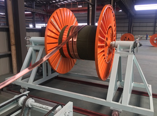
Function:
Place the copper bar coil
Features:
The pay-off frame with motor can receive signal from PLC and swing left and right with cable tray, so when pay off, the copper bar is in the center line of the drawing.
The spool is fixed by the thimbles; one terminal is assembled with the tension device to maintain suitable tension, to make sure the bus bar will be de-coiled smoothly, to avoid the stretches between the bus bars. Another side thimble is movable. When the spool is lifted to the proper position, the thimble can be adjusted by the hand wheel to fix the spool.
Configuration:
1
|
Motor
|
2.2kw
|
2
|
Cable tray specifications
|
PN1600
|
4.2 Guide stand
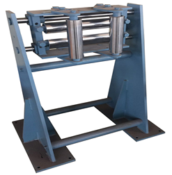
Function:
It is used to change the traverse direction by the proximity switches at two sides.
Features:
The bus bar passes through one set of vertical and horizontal rolls to avoid the stretches from the machine body.
4.3 Straightening and feeding machine
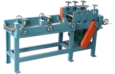
Function:
The machine can straighten the flat and side faces of copper bar, with the traction power installation, the machine can drag the first copper bar through the die lip.
Features:
The machine can decrease the labor intensity of operator, and ensure that copperlocated around the drawing center line during drawing.
Configuration:
1
|
Motor
|
4kw
|
2
|
Straightening roller
|
Plating hard chrome
|
4.4 Cooling and lubricating system of die
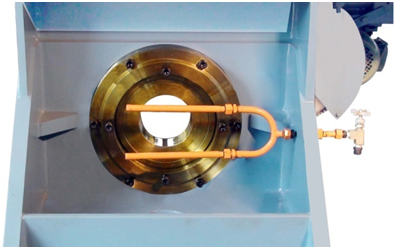
Function:
Lubricate and cool the copper bar and die during drawing.
Features:
The gear pump provides oil supply, with cooling lubricant in automatic circulation.
4.5 Main drawing machine
4.5.1 Clamping jaw
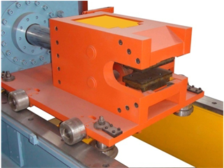
Function:
Clamp the copper bar for drawing
Features:
Raw copper bar is pulled by clamping jaw and pass the die with specific shape, accurate size and surface roughness. After drawing, new copper bar will have specific section and surface quality.
Clamping jaw will be pulled by main hydraulic cylinder. Eight wheels on drawing table will do round moving on the flat rail.
Configuration:
1
|
Wheel
|
45#,high temperature and high-frequency quenching |
2
|
Tooth plate
|
4.5.2 Rail of the drawing table
Features:
The flat rail structure decreases the friction between the roller and the rail, so as to lengthen the service life of the rail.
Configuration:
Good medium carbon steel.
4.5.3 Saw cutting device
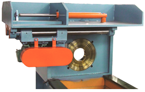
Function:
Cut copper bar after drawing stop
Features:
Under the precondition of the drawing stop, receiving signal from PLC, the pressure release of main hydraulic cylinder and the deliver car in place, saw cutting device cut off copper bar. It will release the air cylinder of clamping jaw and make jaw open. Small piece of copper bus bar will stay in the mouth of die for clamping of next drawing
Configuration:
1
|
Motor
|
3kw
|
4.6 Transport mechanism
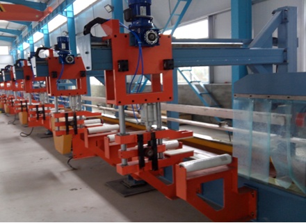
Function:
After drawing, copper bar will be cut down. The copper bar will move to conveyor roller. By conveyor roller, copper bar will move to cutting machine for cutting
Features:
The mechanical arm of deliver car will move forward one by one. They will move back together. The speed can be adjustable. Each deliver car has one frequency converter which is used to adjust moving speed and the synchronization.
The mechanical arms combined clamping the bus bar and move crosswisely by the gears and liner bearing. It makes sure the bus bar will be always at the center during clamping
Configuration:
1
|
Quantity of deliver car
|
6 sets
|
2
|
Motor of deliver car |
0.55kw
|
3
|
Driving system
|
3 sets
|
4
|
Motor of conveyer
|
0.55kw
|
5
|
Felt roller
|
Industrial felt
|
4.7 Final product cutting machine
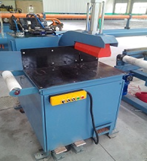
Function:
Cut the final product with saw to be specified length.
Features:
Protective cover will avoid copper chip coming out. This machine has small hydraulic station individually.
Configuration:
1
|
Hydraulic motor
|
1.5kw
|
2
|
Oil pressure
|
8Mpa
|
3
|
Saw motor
|
3kw
|
4.8 Fix-length roll table
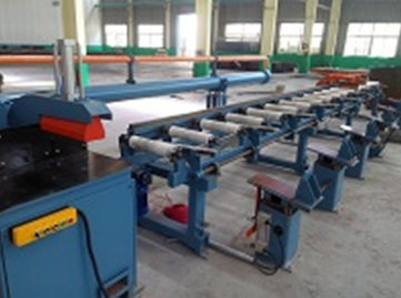
Function:
The final product length is decided by scale backer which can move forward and backward. User would place the position of backer to adjust the length. It can be used for cutting maximum 6 meters long copper bar.
Features:
The transit rolls are all motorized driving.
4.9 Stacking device
Function:
The copper bar after cutting-to-length will be rotated to let copper bar fall into stacking device by unloading arms
Features:
It can go up and down, can stack certain number copper bar according to the size.
Because of the space constraints, the rest cannot be displayed, if you want to know more, please contact us!